I have been participating in the development of solar powered UAV since 2010. The main part of my work is to develop a very light and small autonomous flight control system. Another challenge from controller design perspective is to develop a control law for an aircraft with a very low wing loading since such an aircraft is very susceptible to atmospheric disturbance.
32 hours & 19 minutes of Flight Duration - June 7~9, 2020
27 hours & 58 minutes of Flight Duration - June 15~17, 2018
Red-tide Observation at Yeo-soo (southern coast of Korea) - Aug. 8, 2018
26 hours & 8 minutes of Flight Duration - June 17~19, 2017
On June 17~19, 2017, our solar-powered UAV achieved a contintuous flight duration of 26 hours and 8 minutes.
12 hour-flight in Winter - January 14, 2012
We also flew our solar UAV for 12 hours on January 14, 2012. One of the main reasons that we were able to achieve this long flight in winter time was the MPPT(Maximum Power Point Tracker) that had been developed over the last year by Prof. Hong, Yeh-sun and his student Kwon, Yong-Chul. Since the day time lasts for only about 10 hours in January, we installed four LEDs on the aircraft in order to do the flight test at night time as well.
12 hours & 15 minutes of Flight Duration - September 25, 2011
On September 25, 2011, our team performed a flight test with the solar powered UAV. Our aim in year 2011 was 12 hours, and we achieved this goal. The UAV took off at 6:03 AM, flew for 12 hours and 15 minutes, and landed safely at 6:18 PM after the sunset. The distance traveled during this period was approximately 393km. (The aircraft could have flown for about 3 hours using its battery without solar power.)
Flight Control System
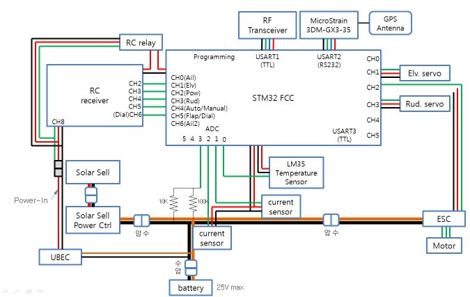
The small and light flight control system was developed. The avionics includes a flight control computer(FCC), a wireless modem, and flight sensors such as GPS and AHRS.
A couple of current sensors were also installed in order to see the flow of the electric current in the power system, and an LM35 sensor was installed to monitor the temperature of the electric motor. A separate BEC and an RC relay has been added in order to remotely switch on/off the FCC. The total weight of the developed avionics was under 200 grams including all the associated wires.
Later, we added a device to measure the rotational speed (rpm) of the motor. The following circuit with a phtotoreflector was used for this purpose. This circuit is connect to the USART3 in the above figure.
Flight software was developed using our hardware in-the-loop simulation (HILS) setup. There are a number of computers involved in the HILS including:

Guidance and Control
The nonlinear path-following guidance method is adopted for the aircraft to follow a circular path during the autonomous mode with the inner loop bank angle control. Elevator control input is composed of a trim value plus a perturbation. The perturbation value is for a feedback control to suppress the plane's phugoid mode, and the the trim value was devised such that it can be set manually. Propeller motor power input was used to close the loop for altitude control.
< Preicison Guidance and Control: Flight data while the airplane was flying along a circle making more than sixty laps during a two-hour autonomous flight segment>
Thermal
One of the benefits of using propeller power (instead of elevator) in closing the altitude loop is to take advantage of the rising air current (=thermal), that can occasionally occurs. When the aircraft comes across such a thermal it gets higher while the power command drops to saturate at the idle (as shown below). Then, the aircraft flies along a helical path since the plane's position is controlled on the cylindrical surface by the nonlinear path following guidance law which is used in the lateral/directional motion.
Autonomous Landing Approach
Autonomous landing approach is also implemented. The primary purpose of this function is to help a safe landing at night hours. From any initial position of the aircraft when this function is engaged, a flight path command is generated that will lead the aircraft to one end of the runway for a landing approach.
A series of flight tests was performed including this one shown below. In this case the aircraft stayed in the first circular path in order to lose an initial altitude. Then it continued to follow the straight line segment and the second circular arc to approach to the runway. Finally the aircraft followed the last straight line segment until the control is taken over to a human pilot for a flare and touchdown.
< Flight Data: Autonomous Landing Approach >
Airplane
The plane we have been testing in 2011 is a modified version of a commercially available RC airplane, Pulsar from F5 Models. We've done many modifications including the solar cell installation to make it an autonomous solar powered UAV. The solar cell system can deliver up to 70W of power while the electric power required for a level flight is 30W. Our team has a plan to build our own design in the near future.
Related Media Press
Acknowledgement
KAU SPUAV (Korea Aerospace University - Solar Powered Unmanned Aerial Vehicle)
: a new aircraft that we are currently working on. The wing span is almost 6 meters. It flies so gorgeously...
Last Update - June 11, 2020